


Editor’s Note
Learning how to use a multimeter can feel confusing at first. After reviewing common questions from multimeter users, our team found that many beginners want to understand the tool itself before following the test steps.
This guide is designed to be your foundational roadmap. Instead of jumping straight into complex tests, we start by decoding the symbols and explaining how each part of the tool works. By mastering these essentials first, you’ll gain the clarity and confidence to tackle everyday electrical issues safely.
If you prefer a visual walkthrough, watch this short video first. It shows the basic setup before you follow the written steps below.
What is a Multimeter
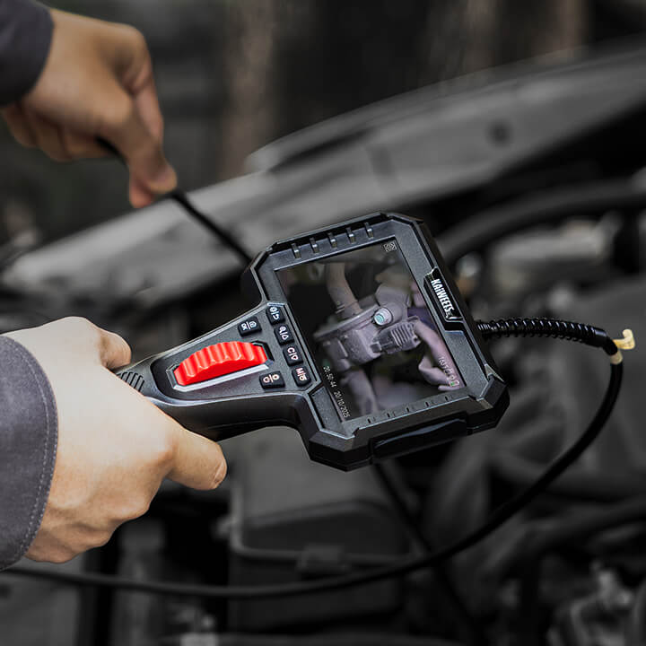
A multimeter is an electrical measuring tool used to test and measure different values in a circuit. Depending on the model, it can measure voltage, current, resistance, continuity, and other electrical properties.
The name “multimeter” comes from its ability to perform multiple measurements with one device. In the past, technicians often used separate tools such as voltmeters, ammeters, and ohmmeters. A multimeter combines these basic functions into a single instrument, making it easier to diagnose electrical problems.
Multimeters are used by electricians, technicians, engineers, mechanics, and DIY users. You can use one to check a battery, test an outlet, find a broken wire, inspect a fuse, troubleshoot automotive wiring, or verify whether a circuit is working as expected.
Types of Multimeters
Multimeters are mainly divided into two types: analog multimeters and digital multimeters. They work and display readings in different ways.
Analog vs. digital multimeters

An analog multimeter uses a moving needle and a printed scale. The needle movement can help you see whether a value is rising, falling, or changing, but the scale can be harder for beginners to read.
A digital multimeter, or DMM, uses electronic circuits to show the measurement as numbers on a screen. This makes it easier to read and understand, which is why digital multimeters are more common for beginners and everyday use.
Common Digital Multimeter Formats
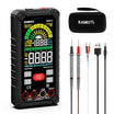
When people talk about a “multimeter” or “digital multimeter” in everyday use, they usually picture a portable handheld device. However, digital multimeters are not limited to one format. They generally come in three main form factors:

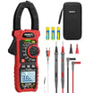
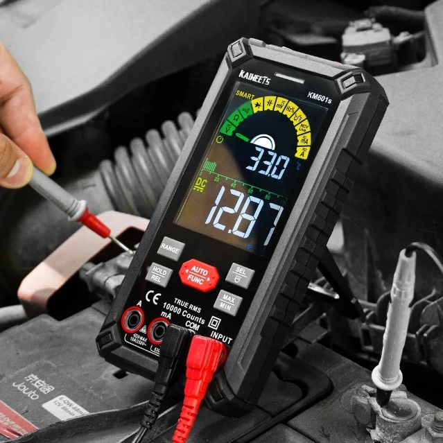
Handheld Multimeter
The Field Essential
- Best For: Electricians, HVAC, and DIYers.
- Power: Battery-powered for portability.
- Advantage: Ruggedized and one-handed use.

Benchtop Multimeter
The Laboratory Standard
- Best For: Lab R&D and electronics repair.
- Power: AC-powered (Wall outlet).
- Advantage: Extreme precision and stability.

Modular Multimeter
The System Integrated
- Best For: Automated testing & ATE systems.
- Power: Powered by host chassis.
- Advantage: Programmable and scalable.
For the rest of this guide, we will focus on handheld digital multimeters. They are the type most beginners and DIY users are likely to own, and they are the most common choice for everyday troubleshooting.
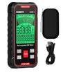
Parts of a Digital Multimeter
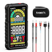
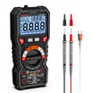
Before we dive into how to use it, let’s get familiar with the interface. A digital multimeter might look complex with all its buttons and symbols, but it generally consists of four main parts on the front and a power source on the back.

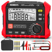
The Interface (Front View)
- Display: This is where you see the measurement readings.
- Control Buttons: Many newer or more advanced digital multimeters include buttons for extra functions, such as Hold to freeze a reading, Max/Min to track changing values, or a mode button to switch between related functions. Simpler meters may have fewer buttons, or may rely mostly on the dial.
- Dial or Selection Knob: The heart of the meter. You rotate this dial to select the type of measurement you want to make (Voltage, Resistance, Current, etc.).
- Input Jacks: These are the ports where you plug in your test leads. (Note: We will decode the small letters next to these jacks in the symbols section below).
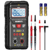
Battery Compartment (Rear View)
The power that drives your multimeter comes from the back.

Most handheld multimeters are protected by a removable rubber sleeve (shockproof cover). To access the battery compartment, you usually need to:
- Remove the rubber protective case.
- Unscrew the back panel using a small screwdriver.
- Install the batteries (typically AAA or a 9V battery).
Note: Many new multimeters come with the batteries uninstalled for safety during shipping. Make sure to pop them in before your first use!
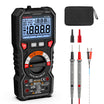
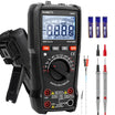
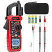
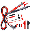
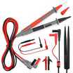
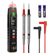
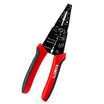
Test Leads
To measure anything, you’ll need to use the Test Leads (also called probes). These are the two flexible wires—one red and one black—that connect the multimeter to the device you're testing.

- Black Lead: Always plugs into the COM (Common) jack.
- Red Lead: Plugs into the appropriate jack for voltage, resistance, or current.
Probe Tips: The metal tips are what you touch to the circuit. High-quality leads often come with protective caps to prevent accidental short circuits while testing.
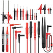
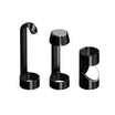
Common Multimeter Probe Types
Besides standard test leads, there are several common probe types you can choose from depending on the job. You do not need all of them for basic use, but they can make certain measurements easier and safer.

- Standard Test Probes: The most common probes for general electrical work.
- Needle-Tip Probes: Thin, sharp probes for reaching small terminals, tight spaces, or crowded circuit boards.
- Alligator Clips: Clip-on leads that grip onto wires or screw terminals, allowing for easy, hands-free testing.
- Tweezer Probes: Specialized tweezer-shaped tips used for grabbing and testing tiny surface-mount devices (SMD).
- Hook Test Clips: Mini spring-hooks that grab onto small wires or component pins and hold tight while you measure.
- Temperature Probe: A sensor probe used with a compatible multimeter to measure temperature.
A Quick Look at Multimeter Symbols and Labels
A multimeter uses short symbols and labels to save space on the dial and around the input jacks. You do not need to memorize every advanced marking right away, but you should understand the basic symbols before making your first measurement.
For a deeper breakdown of safety marks, dial icons, input jack labels and button symbols, see our full guide to multimeter symbols explained.
Common Dial symbols
The image below summarizes 15 common dial symbols you are likely to see on a digital multimeter.

After you learn the basic symbols, you may also notice that some multimeter dials include range numbers, such as 2V, 20V, 200Ω, or 2kΩ. This is where manual-ranging and auto-ranging multimeters differ.
QUICK COMPARE: Manual vs. Auto-Range
Before moving forward, check your meter's faceplate to see which type you own:

- Manual-Ranging: Packed with specific range numbers. Requires you to manually select the correct threshold before touching the circuit.
- Auto-Ranging: No range numbers on the dial. Just select the core symbol. Perfect for hassle-free measurements.
Common Input Jack Labels
The small text printed next to the input ports tells your test leads exactly where to go. Plugging a lead into the wrong jack is the quickest way to blow an internal fuse or get a completely wrong reading.

Overview of the COM, mAVΩ and 10A input jacks on a digital multimeter. Image credit: KAIWEETS.
Let's break down the three primary jacks found on almost every standard multimeter:
- COM (Common): This is the Negative (-) or ground port. Your black test lead always goes here, no matter what type of test you are performing.
- mAVΩ (or VΩmA): This is the standard Positive (+) input jack. For most beginner-level tests, this is the jack you will use most often, including measuring Voltage (V), Resistance (Ω), Continuity, and small currents in milliamperes (mA).
-
10A: This is a high-current dedicated positive (+) jack. You only use this when measuring large amounts of electrical current that would otherwise burn out the standard
mAVΩcircuitry.
Some meters also print safety labels near the jacks, such as MAX 600V, 10A MAX, FUSED or UNFUSED. FUSED means the input is protected by an internal fuse. If too much current flows through that input, the fuse may blow to help protect the meter.
Quick Reference: How to Plug In Your Probes
To make things foolproof, here are the only two probe configurations you will need for basic electrical tests:
Configuration A: Standard Testing

Setup: Black lead in COM | Red lead in mAVΩ
Best For: Voltage, Resistance, Continuity, and Small Current (< mA). (Your go-to setup for 95% of tests).
Configuration B: High-Current Testing

Setup: Black lead in COM | Red lead in 10A
Best For: Measuring heavy electrical current up to 10 Amps. (Never measure voltage with this setup!)
How to Use a Multimeter
This section covers a few basic multimeter tests to help beginners get comfortable with the tool. Instead of going through every advanced function, we will focus on the measurements most people use first: continuity, resistance, voltage and current.
These simple tests help you learn the basic workflow of using a multimeter:
- Plug the test leads into the correct jacks.
- Select the right setting on the dial.
- Touch the probes to the correct test points.
- Read the measurement on the display.
How to Test Continuity Using a Multimeter
Continuity means there is a complete path for electricity to flow. A continuity test is commonly used to check whether a wire, fuse, switch or connection is open or broken.
For a beginner-friendly demonstration, start with a short piece of wire. A good wire should conduct from one end to the other, so the multimeter should beep or show a very low resistance reading when the probes touch both ends.
Safety First: Always make sure the wire or component is not connected to any power source. Continuity mode should only be used on de-energized circuits or components.
- First, plug the black lead into the COM jack and the red lead into the VΩ jack, or the input marked for voltage, resistance and continuity.
- Then turn the dial to the continuity setting. This symbol often looks like a sound wave, speaker or beeper icon.

- Perform a Self-Check: Before testing the wire, touch the two probe tips together. If the meter beeps or shows a value close to 0Ω, the meter and test leads are working properly. This quick check is a good habit before using a multimeter for any basic test.
- Next, touch one probe to each end of the wire.
- If the meter beeps, the wire has continuity. This means the path is complete.
- If the meter stays silent, or the display shows OL, the path is open or broken.
If your multimeter does not have a beep function, set it to the lowest resistance range instead. A reading close to 0Ω usually means the path is continuous. A very high reading or OL means the path is open.
How to Check Resistance Using a Multimeter
Resistance measures how much a component limits the flow of electrical current. It is measured in ohms, shown by the Ω symbol. A resistance test is commonly used to check resistors, sensors, heating elements and other components.
For this demonstration, we will use a standard 2kΩ (2000-ohm) fixed resistor.
Tips: Make sure the component is not connected to any power source. Resistance should only be measured on a de-energized circuit or component. If the part is still connected inside a circuit, other components may affect the reading, so it is often better to test the component separately or disconnect one side first.
- Insert the Leads: Plug the black lead into the COM jack. Plug the red lead into the VΩ jack.
- Select Resistance Mode: Turn the dial to the Ω (Ohm) zone.
- Choose the Right Range: If your meter is manual, select a range slightly higher than the expected resistance. For a 2kΩ resistor, turn the dial to the 20kΩ setting. (If your meter is auto-ranging, simply select the Ω icon).
- Test the Component: Touch the probe tips to the two metal legs of the resistor. The orientation does not matter—resistors do not have positive or negative sides.

Keep your hands off the metal probe tips while taking the measurement. Your body has its own electrical resistance. If you pinch the tips with your fingers, your body's resistance will blend with the component's, ruining the accuracy of your test.
- Expected Reading: The screen should stabilize rapidly at around 1.97 to 2.03 (representing ~2kΩ). It is normal for a resistor to vary slightly from its rated value due to manufacturing tolerances.
- If the screen displays "OL" (Over Limit): The resistance is higher than the selected range (turn the dial to a higher setting) or the component is completely broken (open circuit).
How to Test for Voltage Using a Multimeter
Voltage measures the electrical potential difference between two points. In simple terms, it tells you how much electrical “pressure” is available in a circuit.
We will focus on Direct Current (DC) voltage, which is the type of electricity stored in batteries and used by most household electronic gadgets.
For a simple demonstration, we will use a fresh 1.5V AA battery. A battery is a safe, low-voltage example, and the positive and negative ends are easy to identify.
- Insert the Leads: Keep the black lead in the COM jack and the red lead in the VΩ jack.
- Select DC Voltage Mode: Turn the dial to DC voltage, often marked as V⎓, DCV or a similar symbol.
- If your multimeter is manual-ranging, choose a range higher than the expected voltage. For a 1.5V battery, the 2V or 20V range is a good choice, depending on your meter.
- Test the Battery: Press the red probe firmly against the positive terminal (+) of the battery, and the black probe against the negative terminal (-).

- A Healthy Battery: A new 1.5V battery will typically show a reading between 1.49V and 1.6V.
- A Dead Battery: If the reading drops significantly below 1.3V, the battery is running low or dead.
What if the Reading is Negative?
If your multimeter screen shows a minus sign (e.g., -1.5V), do not worry. This simply means your probes are reversed (the black probe is on the positive terminal). It is completely safe. Just reverse the probes to get a positive reading, or ignore the minus sign.
When measuring higher voltages, such as household AC voltage, use extra caution and make sure your multimeter and test leads are properly rated for the job. For this beginner guide, it is best to practice first with low-voltage DC sources such as batteries.
How to Measure Current Using a Multimeter
Current measures how much electricity is flowing through a circuit. It is measured in amps, shown as A, mA or µA. Current measurement is useful, but it is also the multimeter test beginners are most likely to do incorrectly.
Current is different from voltage. Voltage is measured across two points, but current must be measured in series (in line). That means the circuit has to be opened, and the multimeter must become part of the path so current flows through the meter.
For a safe beginner demonstration, use a simple low-voltage circuit made with a battery, an LED, a resistor and a few jumper wires. The resistor is important because it limits current and helps protect the LED.
- Move the Red Probe (CRITICAL): Leave the black lead in COM. Unplug the red lead from VΩ and move it into the mA port (or the 10A port if you expect a high current draw).
- If you are not sure which current input to use, start with the higher-current input and range, then move lower if needed.
- Select DC Current Mode: Turn the dial to DC current, often marked as A⎓, DCA or a similar symbol. Since the demonstration circuit uses a battery, use the DC current setting.
- Break the Circuit: Disconnect one wire in your working circuit to turn the LED light off. This creates an open "gap" in your loop.
- Connect in Series: Touch the red probe to the side connected to the power source and the black probe to the side connected to the LED. The multimeter will act as a bridge. The LED will light back up, and the meter will measure the current flowing through it.
Crucial Safety Rule
Never touch the probes directly to the positive and negative sides of a battery while the meter is set to Current mode. Doing so creates a short circuit, which will instantly blow the internal fuse of your multimeter or damage the tool permanently.
Always remember to plug the red lead back into the VΩ jack as soon as you finish your current test, so you don't accidentally short-circuit a circuit during your next voltage test.
For beginners, current measurement should be practiced only on simple, low-voltage circuits. Do not use household mains voltage or high-current circuits for practice.
How to Replace a Multimeter Fuse
If a multimeter stops measuring current, a blown fuse is often the reason. This can happen when the red lead is in the mA or A jack and the meter is accidentally connected across a battery, power supply or outlet instead of being connected in series.
Replacing the fuse is a simple maintenance task, and it also helps you understand the basic internal structure of the meter.
Before opening the meter, turn it off, remove the test leads and disconnect it from any circuit.
Step 1: Remove the Protective Case

Remove the test leads from the multimeter and make sure the meter is turned off. If your multimeter has a rubber protective case, gently pull it off first. This gives you access to the screws on the back of the meter.
Step 2: Remove the Back Cover Screws

Use a small screwdriver to remove the screws on the back cover. Keep the screws in a safe place so they do not get lost.
Step 3: Open the Cover and Locate the Fuse

Carefully remove the back cover. Inside the multimeter, look for the fuse holder or fuse clips. The fuse is usually a small glass or ceramic tube mounted on the circuit board. Avoid touching other parts of the circuit board unless necessary.
Step 4: Remove the Old Fuse

Use a small flathead screwdriver or a plastic tool to gently lift one end of the fuse out of its holder. Do not force it, because the fuse clips can bend or break. Once one end is loose, remove the fuse by hand.
Tip: If the fuse looks dark, cracked, or the thin wire inside is broken, it is likely blown. However, some fuses may look normal even when they are bad, so testing the fuse with another multimeter is more reliable.
Step 5: Check the Label for the Right Specification

Many multimeters come with two fuses: one for low current (mA/μA) and one for high current (10A/20A). Look closely at the markings printed on the circuit board, usually right under or next to the fuse slots, so you don't put the wrong fuse into the wrong place.
- No Polarity: Fuses do not have "positive" or "negative" sides. You can insert them in either direction, and they will work perfectly fine.
- Check the rating before replacement: Also check the small labels next to the current input jacks on the front of the multimeter. These labels usually show the current and voltage limits for each input, such as 10A/250V or 800mA/1000V. The replacement fuse should match the original fuse in current rating, voltage rating, size, and type. Common fuse sizes include 5×20 mm, 6×30 mm, and 6.3×32 mm.
After confirming the correct fuse, install the new one into the holder, close the back cover, tighten the screws, and put the rubber case back on.
Multimeter Practice Questions
Test what you have learned so far. Choose an answer to see the explanation, then move to the next question.


Leave a comment
All comments are moderated before being published.
This site is protected by hCaptcha and the hCaptcha Privacy Policy and Terms of Service apply.