


A multimeter cannot fully test a PCM by itself. It can help you check the basic electrical conditions that the PCM depends on.
- Check battery voltage before testing the PCM.
- Verify PCM power and ground circuits.
- Use a scan tool to confirm trouble codes.
What Is a PCM on a Car?
A PCM is the computer that manages the vehicle’s powertrain. It uses sensor signals to control engine operation and, on many vehicles, transmission behavior.
The exact name can vary by manufacturer. Some vehicles use the term PCM. Others use ECM or ECU. In repair conversations, these terms often refer to the module that controls engine operation.
Modern OBD-II systems also store diagnostic trouble codes when faults are detected. The California Air Resources Board explains that OBD-II monitors emission-related components and turns on the warning light when a fault is found. You can read more in the CARB OBD II systems fact sheet.
Because the PCM works with many circuits, symptoms alone are not enough to condemn the module. A weak battery, bad ground, or damaged connector can look like a PCM failure.
If you suspect a PCM issue, start with basic electrical checks. Then confirm the result with scan-tool data and the service manual for your exact vehicle.

Can You Test a PCM With a Multimeter?
You can test the PCM’s supporting circuits with a multimeter. You should not try to test the sealed PCM circuit board as a normal DIY repair step.
A PCM is not a simple switch or fuse. It contains electronics and software. A multimeter can help you find missing power, poor ground, or an abnormal reference voltage. It cannot verify the internal programming of the module.
| Multimeter Check | What It Can Tell You | What It Cannot Prove |
|---|---|---|
| Battery voltage | The vehicle has enough basic supply voltage. | The PCM is internally good. |
| Continuity | A wire may not be open. | The circuit works correctly under load. |
| Voltage drop | A live circuit has unwanted resistance. | The PCM software is faulty. |
| 5-volt reference | The reference circuit is present. | The PCM is the only possible cause. |
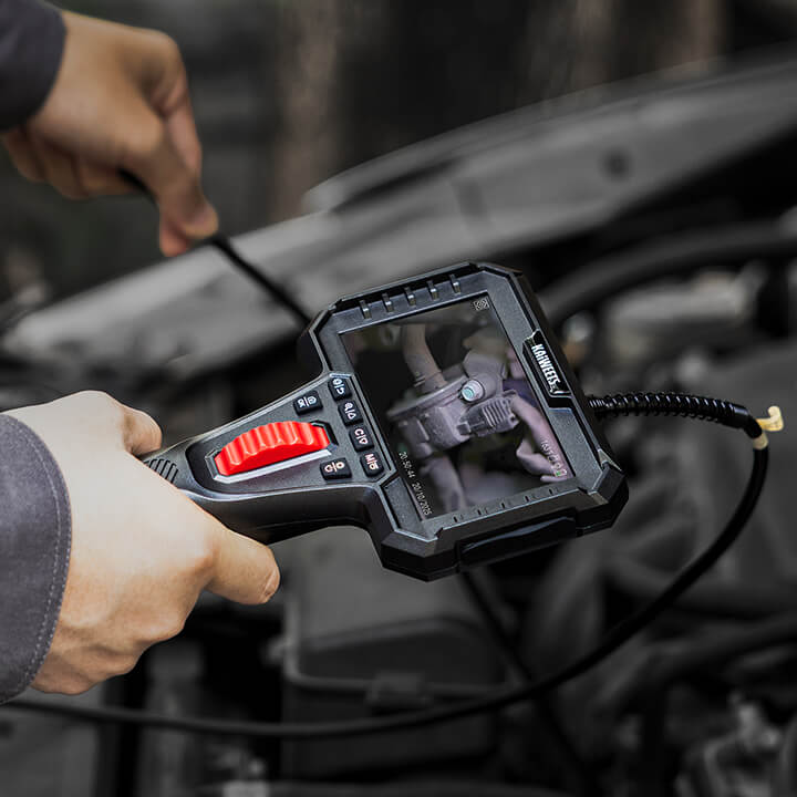
How Do You Test a PCM With a Multimeter?
You test a PCM by checking the power, ground, and reference circuits that feed it. Do not open the PCM case or probe random pins without a wiring diagram.
Before you start, park the vehicle safely and keep metal jewelry away from the battery. Use the correct meter setting. If you are not comfortable with basic voltage and resistance checks, review our guide on how to use a multimeter first. If you are not sure which pin to test, stop and check the service information first.
-
Read the trouble codes first.
A scan tool should be used before the multimeter. Record the codes and freeze-frame data. This helps you choose the right circuit instead of guessing.
-
Check battery voltage.
Set the multimeter to DC volts. A fully charged 12-volt battery is usually close to 12.6 volts with the engine off. With the engine running, many charging systems read around 13.5 to 14.5 volts. Always compare your reading with the vehicle specification.
-
Check the PCM fuse and relay feed.
With the key in the correct position, test both sides of the relevant fuse. If one side has voltage and the other does not, the fuse may be open.
-
Verify power at the PCM connector.
Use the wiring diagram to identify the PCM power pin. Back-probe carefully. The reading should be close to battery voltage when that circuit is supposed to be active.
-
Check the PCM ground circuit.
Use a voltage-drop test with the circuit connected. A good ground path should show very little voltage loss. If the reading is high, the problem may be in the ground path rather than the PCM.
-
Check the 5-volt reference circuit.
Many sensors use a 5-volt reference from the PCM. If this circuit is pulled low, unplug the related sensor only when the service manual tells you to do so. A shorted sensor can make the PCM look bad.
-
Recheck before replacing the PCM.
If power and ground are correct, confirm the fault with scan-tool data. Some PCM-related problems are fixed with repair procedures or software updates.
How Do You Run a Voltage Drop Test on a PCM Power Circuit?
A voltage drop test checks how much voltage is lost while the circuit is working. This is better than a simple continuity test because it tests the circuit under load.
For a PCM power circuit, keep the connector plugged in when the service manual allows back-probing. Set the multimeter to DC volts. Measure between the battery positive post and the PCM power feed pin.
A high reading means voltage is being lost before it reaches the PCM. The fault may be before the module, so replacing the PCM would not fix the root problem.
For a PCM ground circuit, measure between the PCM ground pin and the battery negative post. A high reading means the ground path has too much resistance.
If you need a simple tool to confirm whether voltage is present in a circuit, a voltage tester can be helpful. For diagnosis, a digital multimeter gives more useful readings.
What Voltage Readings Should You Expect When Testing PCM Circuits?
Expected readings depend on the vehicle and the exact circuit. Use the table below as a general starting point, then verify the specification in your service manual.
| Test Point | General Reading | What an Abnormal Reading May Mean |
|---|---|---|
| Battery at rest | About 12.6 volts when fully charged | The battery may be weak or discharged. |
| Battery with engine running | Often about 13.5 to 14.5 volts | The charging system may need testing. |
| PCM power feed | Close to battery voltage | The feed circuit may be open or restricted. |
| PCM ground voltage drop | Very low under load | The ground path may have resistance. |
| 5-volt reference | About 5 volts on many vehicles | The reference circuit may be shorted. |
Battery voltage ranges are only a baseline. The correct charging voltage still depends on the vehicle design.
What Are the Symptoms of a Faulty PCM?
A faulty PCM can cause drivability problems, but the same symptoms can also come from wiring or sensor faults. Treat these signs as clues, not proof.
| Symptom | Why It Is Not Proof by Itself |
|---|---|
| Check engine light stays on | The code may point to a circuit problem. |
| No-start condition | A missing power feed can stop communication. |
| Intermittent stalling | A relay or ground fault may act the same way. |
| Rough idle | A sensor fault can cause unstable operation. |
| Failed readiness monitors | The vehicle may need a drive cycle. |
When Should You Stop Testing and Call a Mechanic?
You should stop testing if the diagnosis requires module programming, advanced scan data, or safe access to high-risk systems. Guessing at this stage can damage the vehicle.
- Stop if the scan tool cannot communicate with the vehicle.
- Stop if you find water damage near the control module.
- Stop if the vehicle is a hybrid or EV and the test area is unclear.
- Stop if the service manual requires factory-level programming.
Before replacing the PCM or any control module, check for open recalls or manufacturer service updates for your specific vehicle. Some module-related problems are fixed through dealer service or software updates, so this step can help you avoid replacing an expensive part unnecessarily.
Frequently Asked Questions
Is It Safe to Test My PCM With a Multimeter?
Yes, basic PCM circuit testing can be safe if you use the correct procedure. Keep the connector plugged in when back-probing is required, and do not short adjacent pins.
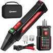
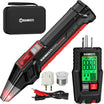
What Kind of Multimeter Should I Use to Test PCM Circuits?
Use a digital multimeter that can measure DC voltage and resistance accurately. An auto-ranging multimeter is convenient for most basic automotive electrical checks.
Can a Multimeter Confirm That a PCM Is Bad?
No, a multimeter cannot confirm every internal PCM failure. It can show whether the module has proper voltage and ground, which helps rule out simpler faults first.
Do I Need an OBD-II Scanner to Diagnose a PCM Problem?
Yes, an OBD-II scanner is strongly recommended. A scanner reads trouble codes and live data, while a multimeter checks the electrical side of the circuit.
Should I Replace the PCM If Power and Ground Look Good?
No, not immediately. Confirm the diagnosis with service-manual tests, scan-tool data, and any relevant software information before replacing the module.
Conclusion
Testing the PCM with a multimeter is best understood as testing the circuits around the PCM. Start with the battery, then verify power and ground at the module.
If those checks are normal, do not assume the PCM is bad. Use scan-tool data and the vehicle service manual before replacing any control module. This approach is safer, more accurate, and less likely to waste money on an unnecessary PCM replacement.

Leave a comment
All comments are moderated before being published.
This site is protected by hCaptcha and the hCaptcha Privacy Policy and Terms of Service apply.