













































What is Transformer?
A transformer is a machine that uses electromagnetic induction to move electricity between two or more circuits. In electric power applications, transformers are used to increase or decrease the alternating voltages. Transformers are used in a wide range of electronic devices, such as radios, TVs, computer networks, and power supplies.
There are two types of transformers:
- Step-up: increase the voltage.
- Step-down: decrease the voltage.
The primary winding is wrapped around the core, while the secondary winding is wound around the primary. The number of turns in the primary winding determines the voltage transformation ratio, which is calculated as the number of turns in the secondary winding divided by the primary winding. The secondary winding connects to the load, while the primary connects to the power source.
Since transformers are critical components in electrical systems, ensuring their proper functioning is essential for the safety and efficiency of the entire system. Regular testing helps identify potential issues before they cause significant damage. Now, let's dive into the steps for testing a transformer using a multimeter to ensure its integrity and safe operation.
Tools Required for Testing a transformer
- A multimeter
- A transformer

Transformer Testing with a Multimeter
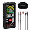
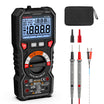
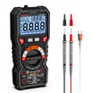
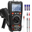
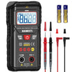
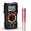
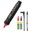
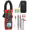
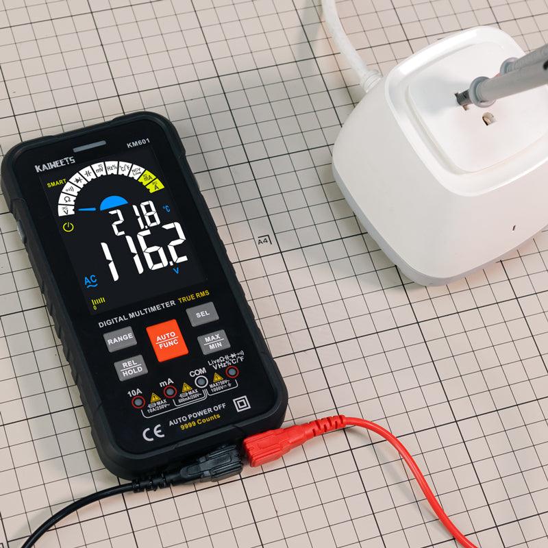
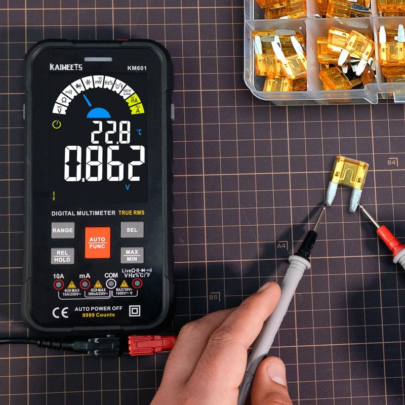
If you are new to electrical testing, take a moment to review how to use a multimeter safely before checking a transformer. A little preparation makes the resistance and continuity readings in the next steps much easier to understand.
Always disconnect the transformer from the power source before testing resistance. Measuring a live circuit will damage your multimeter and pose a shock hazard.
1. Set the Multimeter to Ohms (Ω)
Turn the dial to the Resistance (Ω) setting. If your meter is not auto-ranging, start with a low range (e.g., 200Ω) for the secondary and a higher range (e.g., 2kΩ) for the primary.
2. Test the Primary Winding (Continuity Check)
Touch one lead to each end of the primary winding terminals.
- Healthy Reading: You should see a stable resistance. Depending on the transformer size, this could range from 10Ω to 500Ω.
- Faulty Reading: If the meter displays OL (Open Loop), the primary coil is broken (blown). If it reads 0.0Ω, the winding is internally shorted.
3. Test the Secondary Winding (Continuity Check)
Touch the leads to the secondary winding terminals.
- Healthy Reading: Usually, the secondary resistance is much lower than the primary in step-down transformers (often 1Ωto 20Ω).
- Faulty Reading: Again, OL indicates a failed, open circuit.
4. The Isolation Test (Critical Safety Step)
A transformer may have continuity but still be dangerous if the insulation has failed.
- Winding to Winding: Touch one lead to a primary terminal and the other to a secondary terminal. The meter MUST read OL. Any resistance value here indicates an internal short between the two circuits.
- Winding to Ground (Core): Touch one lead to a winding terminal and the other to the metal frame or iron core. This MUST also read OL. If you get a resistance reading, the transformer is "leaking" electricity to the chassis and is a fire/shock hazard.
Signs of Transformer Failure
Identifying early warning signs can prevent catastrophic equipment failure and electrical fires. Watch for the following symptoms:
- Excessive Heat: While transformers naturally warm up during use, an unusually high operating temperature or a "burnt" smell often indicates an internal short-circuit or an overload condition.
- Abnormal Noise: A healthy transformer should produce a faint, steady hum. Loud buzzing, clicking, or vibrating sounds (often called "transformer hum") suggest loose internal laminations or hardware.
- Visual Damage: Inspect the unit for bulging casings, discolored (charred) wire insulation, or any signs of leaked dielectric fluid in larger units.
- Performance Drops: Frequent tripping of circuit breakers or inconsistent output voltage are clear indicators of internal degradation.
Common Transformer Testing Questions
Is it necessary for a transformer to have continuity?
Yes, a transformer should have continuity to ensure uninterrupted current flow. A break in continuity can lead to current surges, which may damage the transformer or cause an electrical fire. Regular continuity checks help prevent such issues.
How do you test a transformer for failure?
There are several ways to test a transformer for failure:
- Loss of Charge Test: Measure the voltage across the transformer’s terminals with a voltmeter when the transformer is turned off. A significant loss of charge may indicate an issue.
- Current Flow Test: Measure the current flowing through the transformer using an ammeter when the transformer is powered on. Abnormal current readings can signal internal issues.
- Resistance Test: Use an ohmmeter to measure the resistance of the transformer’s windings. A high resistance or lack of continuity indicates a fault.
If any of these tests show improper readings, the transformer likely needs replacing.
What are the types of transformer testing?
There are four main types of testing typically performed on transformers:
- No-load Test: Measures the iron losses and magnetizing current when the transformer is not under load.
- Load Test: Verifies the transformer’s ability to operate safely under its specified load.
- Insulation Test: Assesses the health of the transformer’s insulation system by measuring resistance to an applied voltage.
- Functional Test: Ensures the transformer performs its intended function, often conducted during commissioning or after major repairs.
More resources

1 comment
shedrick
Very informative article on transformer testing
Leave a comment
All comments are moderated before being published.
This site is protected by hCaptcha and the hCaptcha Privacy Policy and Terms of Service apply.