





























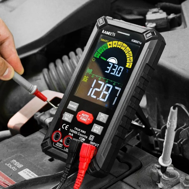
A battery that repeatedly dies while the car is parked may be defective, undercharged, or supplying an electrical load that never shuts off. This guide explains how to distinguish those possibilities and check for parasitic battery drain safely.
What is Parasitic Draw?
Modern vehicles continue using a small amount of electricity after the ignition is turned off. Clocks, alarm systems, keyless-entry receivers, telematics units, and electronic memory all need standby power. This normal consumption is often called key-off draw, dark current, or quiescent current.
A problem exists when the current remains higher than the vehicle was designed to tolerate after its control modules have entered sleep mode. That excessive or unintended load is commonly called a parasitic draw or parasitic battery drain.
Before You Test, Rule Out Other Causes of a Dead Battery
A dead battery does not prove that the vehicle has a parasitic drain. The same symptom can result from several unrelated problems:
- An old, sulfated, internally damaged, or self-discharging battery
- A loose or corroded battery terminal or ground connection
- An alternator or charging-system fault
- A light, heated accessory, inverter, or other device left on
- An aftermarket dashcam, alarm, stereo, tracker, or OBD-II accessory
- Repeated short trips that do not replace the energy used during starting
- Long storage periods, particularly in very hot or cold conditions
- A one-time mistake rather than a recurring electrical fault
Begin with a visual inspection. Look for a swollen or damaged battery case, leaking electrolyte, loose terminals, corrosion, damaged cables, or a slipping drive belt. Do not test or charge a visibly damaged, frozen, or leaking battery.
Next, establish whether the complaint repeats. A battery that went dead once after a dome light was left on does not justify dismantling the electrical system. A battery that loses its charge every night after being fully recharged is much more consistent with a battery failure, charging problem, or abnormal key-off load.
Should You Charge the Battery Before a Parasitic Draw Test?
Yes, if the battery is discharged. A parasitic draw test should begin with a charged, serviceable battery. Low voltage can alter module behavior, trigger battery-protection features, or prevent the vehicle from completing its normal shutdown sequence. Those changes can make the test misleading.
Use a battery charger compatible with the installed battery type. Follow the vehicle manufacturer's instructions for connecting the charger. Some vehicles use a battery-monitoring sensor and require charging through designated underhood points rather than directly at both battery posts.
A conventional 12-volt lead-acid battery generally reads about 12.6 volts when fully charged and rested, although construction, temperature, and recent charging affect the number. If the battery will not accept or hold a charge, have it professionally tested or replace it before continuing.
Once the battery can hold a charge, verify that the charging system operates according to the vehicle's service information. Only then does it make sense to search for an abnormal load while the vehicle is parked.
Tools You Will Need
-
A digital multimeter with fused DC amp and milliamp inputs, plus DC millivolt resolution
- Vehicle-specific service information with the sleep procedure, current specification, fuse layout, and wiring diagrams
- Insulated test leads or alligator clips that remain secure during a long test
-
Protective gloves
A low-current DC clamp meter is useful but optional. It can measure current through the battery cable without disconnecting the battery, which makes it less likely that the test itself will reset a module or temporarily remove the fault. A clamp meter must have adequate low-current resolution; a general-purpose high-current clamp may not measure tens of milliamps accurately.
Essential Safety Rules
Current testing is less forgiving than voltage testing. When a multimeter is set to measure amps, it becomes part of the circuit and has very low internal resistance. Incorrect use can blow the meter's fuse, damage the meter, create sparks, or damage vehicle electronics.
- Use only a current input protected by the correct internal fuse.
- Inspect the meter, leads, and lead insulation before use.
- Start on the highest fused DC-current range, usually the 10A input.
- Never place a meter set to amps directly across the battery terminals.
- Never crank or start the engine while the meter is connected in series.
- Do not turn on the ignition, headlights, blower motor, rear defroster, or another high-current load.
- Do not exceed the meter's current rating or permitted measurement time.
- Return the red lead to the voltage jack after completing the current test.
- Keep sparks, flames, and smoking materials away from lead-acid batteries.
This procedure concerns the 12-volt system. On a hybrid or electric vehicle, do not touch orange high-voltage cables or components. Consult the manufacturer's procedure or use a qualified technician if access to the 12-volt battery requires work near the high-voltage system.
Step 1: Check Battery Voltage
A voltage check cannot prove that a battery has adequate capacity, but it can show whether the battery is charged enough for further diagnosis.
Engine Off
- Place the black lead in the COM jack and the red lead in the voltage/ohms jack.
- Select DC volts.
- Touch the red probe to the positive battery terminal and the black probe to the negative terminal.
- Read the voltage after the battery has rested, following any surface-charge procedure specified by the battery or vehicle manufacturer.
| Voltage | Approximate state of charge |
|---|---|
| 12.6 V or slightly higher | Near full charge |
| About 12.4 V | About 75% |
| About 12.2 V | About 50% |
| Below 12.0 V | Heavily discharged; charge and evaluate before continuing |
These are general references, not pass/fail specifications. Battery chemistry, temperature, recent charging, and battery condition can change the reading.
Engine Running
With the multimeter still configured for voltage—not current—start the engine and check the voltage across the battery terminals. Approximately 13.7 to 14.7 volts is common on traditional charging systems under normal conditions.
Late-model vehicles may use computer-controlled charging that intentionally raises, lowers, or temporarily suspends alternator output. A reading outside the traditional range does not automatically prove that the alternator is defective. Compare the measured voltage with the commanded value and diagnostic procedure in the vehicle's service information.
If the battery is charged and the charging system is operating properly, the next challenge is making sure the vehicle reaches a genuine sleep state.
Step 2: Prepare the Vehicle for Sleep Mode
Many inaccurate parasitic draw test results are actually measurements of a vehicle that is still awake. Opening a door, pressing a key-fob button, touching a keyless-entry handle, or removing a fuse can restart communication between modules.
Prepare everything before beginning the wait:
- Turn off the ignition and remove all keys from the vehicle.
- Switch off every accessory and unplug removable chargers, adapters, and aftermarket devices.
- Lower a window so you can reach the interior without opening a door.
- Open any fuse-box covers you will need during the test.
- Close the doors, hood, and trunk. If they must remain physically open, carefully operate their latch switches according to the service procedure so the vehicle detects them as closed.
- Make sure courtesy, cargo, glove-box, vanity-mirror, and underhood lights are off.
- Lock or arm the vehicle if the manufacturer requires it.
- Move the key fob away from the vehicle. Some manufacturer procedures specify a minimum distance.
- Stay away from door handles and hands-free liftgate sensors while the vehicle powers down.
- Wait for the vehicle-specific sleep period without disturbing it.
Ten to 45 minutes is a common general estimate, but it is not a universal rule. Some vehicles require 25 to 55 minutes, and certain manufacturer procedures call for observations after two hours. Others conduct scheduled emissions, suspension, security, or telematics activity long after shutdown.
Watch the current fall in stages if your equipment allows it. A module may draw several amps immediately after shutdown, then drop through progressively lower levels before reaching its final sleep current. Use the manufacturer's time and current specifications whenever they are available.
Step 3: Connect the Multimeter in Series
The following procedure uses the negative battery cable, which reduces the chance of accidentally shorting a tool between the positive terminal and grounded bodywork. Consult the service manual before disconnecting the battery; some vehicles require special steps to preserve settings or prevent damage.
- Confirm that the ignition and all accessories are off.
- Insert the black lead into COM.
- Insert the red lead into the meter's fused high-current input, commonly marked 10A.
- Select DC amps and the highest available current range.
- Disconnect the negative battery cable without allowing it to touch the negative post again.
- Connect the red meter lead to the disconnected negative cable and the black lead to the negative battery post. If the display shows a minus sign, the leads are reversed; the magnitude is still the relevant value.
- Secure the leads so the circuit cannot open accidentally while you wait.
Negative battery post → Multimeter in DC amps mode → Disconnected negative cable
Step 4: Read and Interpret the Current Draw
Do not diagnose the first number that appears. Initial current may be high because reconnecting the circuit wakes multiple modules. Observe the reading until the manufacturer-specified sleep period has passed and the current has stabilized.
Multimeters may display amps or milliamps. Remember:
            1 amp (A) = 1,000 milliamps (mA)

            0.10 A = 100 mA

            0.05 A = 50 mA

            0.02 A = 20 mA
| Stabilized reading | General interpretation |
|---|---|
| Below 50 mA | Often normal, but verify the exact vehicle specification. |
| 50–100 mA | A gray area. Vehicle equipment, test duration, temperature, and periodic wake events must be considered. |
| Above 100 mA | Commonly suspicious after sleep mode has been confirmed, but still compare it with factory service information. |
The often-repeated rule that anything below 50 mA is normal is only a starting point. Manufacturer procedures differ. For example, published service information has used limits around 40, 50, or 70 mA for particular vehicles and test conditions. A reading must be interpreted in the context of the exact model and the required observation period.
Why Start With the 10A Input?
The high-current input is used first because a recently awakened vehicle may draw more current than the meter's milliamp circuit can tolerate. The 10A input offers less resolution but provides a safer starting point.
Once the vehicle is asleep and you have confirmed that the current is below the meter's milliamp-input limit, the mA range can provide a more precise reading. A common professional meter may permit up to 400 mA through its mA jack, but another meter may be limited to 200 mA or a different value. Use the rating printed on your meter and stated in its manual.
To change inputs, open the circuit and move the red lead to the fused mA jack before selecting the appropriate mA range. Be aware that interrupting the circuit can wake or reset the vehicle. If maintaining an uninterrupted connection is necessary, use the manufacturer-approved procedure or suitable professional equipment.
A high total-current reading confirms that further diagnosis is justified, but it does not identify the failed part. The next step is to determine which circuit carries the unwanted load.
Step 5: Isolate the Affected Circuit
There are two common ways to isolate a parasitic battery drain: measuring voltage drop across installed fuses or removing fuses while watching total current. On modern networked vehicles, voltage-drop testing is usually less disruptive.
Preferred Method for Modern Vehicles: Measure Voltage Drop Across the Fuses
A fuse has a small amount of electrical resistance. When current flows through it, a correspondingly small voltage develops between the two fuse test points. A sensitive multimeter can measure this voltage in millivolts without removing the fuse or interrupting the circuit.
- Leave the battery and all fuses connected.
- Make sure the vehicle has entered sleep mode.
- Move the red meter lead back to the voltage/ohms jack.
- Select DC millivolts.
- Touch one probe to each exposed test point on top of the fuse.
- Record the absolute millivolt reading; probe direction only changes the sign.
- Identify the fuse's physical style and amp rating.
- Use the correct fuse voltage-drop chart to estimate the current through that circuit.
- Compare the estimated circuit current with the excessive total draw.
Voltage-drop testing has limitations. Very small currents may produce a voltage below the meter's usable resolution, and fuse resistance changes with temperature and construction. Treat the chart as a diagnostic aid rather than laboratory-level current measurement. A circuit with no measurable voltage drop is less likely to be responsible for a large continuous drain, but it is not automatically fault-free.
Alternative Method: Pulling Fuses
On a simpler older vehicle—or when the manufacturer specifically directs you to do so—you can remove one fuse at a time while watching the series ammeter. If the total current drops substantially when a fuse is removed, you have identified the affected circuit.
There are important drawbacks:
- Removing or reinstalling a fuse may wake the vehicle network.
- The vehicle may need to complete its entire sleep sequence after each disturbance.
- Disconnecting a module can temporarily clear an electronic fault.
- Removing a fuse may erase learned settings or create diagnostic trouble codes.
For these reasons, several manufacturer procedures instruct technicians to leave the fuses installed and measure millivolt drop instead. Follow the service information for the vehicle in front of you rather than assuming that one isolation method fits every car.
Step 6: Find the Component Causing the Drain
Once you identify the suspect fuse, use the fuse-box legend and a wiring diagram to determine everything that the fuse powers. A single fuse may feed several modules, relays, switches, lamps, or downstream fuses.
Check the most likely causes first:
- Aftermarket alarms, stereos, amplifiers, remote starters, trackers, and dashcams
- USB chargers, power adapters, or devices connected to always-hot outlets
- Glove-box, vanity-mirror, cargo-area, trunk, or underhood lamps
- A relay with contacts stuck closed
- A door, hood, or trunk switch that never reports the closed position
- A module that remains awake because of a fault or network message
- Damaged wiring, water intrusion, or corrosion inside a connector
Disconnect components on the suspect circuit one at a time, following the service procedure. After each disturbance, allow the vehicle to return to sleep before judging the result. When the excessive total draw or fuse voltage drop disappears, inspect that component, its control inputs, and its wiring before replacing anything.
What If No Fuse Explains the Draw?
If the total battery current is excessive but none of the ordinary branch fuses accounts for it, consider:
- An alternator rectifier or another circuit connected through a fusible link
- A starter, power-distribution, or battery-cable fault
- More than one smaller drain operating at the same time
- A control network that never enters sleep mode
- An intermittent load that was not active while the fuses were checked
- A measurement error, open meter fuse, incorrect input jack, or inadequate clamp resolution
An intermittent or network-related drain may require a logging meter, current clamp, oscilloscope, scan tool, or manufacturer-specific diagnostic process. At that point, professional diagnosis is often more efficient than repeatedly disconnecting components.
Step 7: Verify the Repair
Finding a current drop after disconnecting a component is not the end of the job. Restore the vehicle and repeat the test under the same conditions to prove that the fault is gone.
- Reconnect all required components, fuses, cables, and connectors.
- Release any manually closed door, hood, or trunk latches.
- Securely reconnect the battery using the manufacturer's procedure.
- Charge the battery if it was deeply discharged by the fault.
- Prepare the vehicle for sleep mode again.
- Repeat the total-current test and confirm that the final reading meets the vehicle specification.
- Check for diagnostic trouble codes and clear only those created by the approved repair process.
- Perform any required clock, window, sunroof, steering-angle, idle, radio, or battery-management relearns.
For an intermittent complaint, one normal reading may not be enough. Follow the manufacturer's long-term monitoring procedure and distinguish brief scheduled wake events from a sustained abnormal load.
Common Parasitic Draw Test Mistakes
- Testing a discharged battery: Low system voltage can change how modules behave.
- Skipping the battery health test: A battery can show reasonable voltage and still have inadequate capacity.
- Reading too soon: A vehicle that has not entered sleep mode will naturally show higher current.
- Leaving a door or hood circuit active: Courtesy lights and wake signals can invalidate the test.
- Keeping the key fob nearby: Passive-entry systems may continue polling or wake when the handle is approached.
- Starting on the mA input: Initial module current may exceed the small fuse's rating.
- Cranking with the meter in series: Starter current is far beyond a handheld meter's capacity.
- Confusing volts with amps: Battery voltage shows electrical potential; current draw shows the rate of energy use.
- Blindly pulling every fuse: This can wake networked modules and temporarily remove the fault.
- Replacing the fuse: A fuse carrying current is doing its job; the cause is normally elsewhere on the circuit.
- Ignoring aftermarket devices: Added accessories are common sources of unintended key-off loads.
- Using one threshold for every vehicle: Factory specifications override generic 50 mA or 100 mA rules of thumb.
The Bottom Line
A reliable parasitic draw test is more than connecting a multimeter and pulling fuses. Start with a charged, healthy battery and a verified charging system. Prepare the vehicle carefully, wait for true sleep mode, measure current through the correct fused input, and compare the result with the manufacturer's specification.
If the draw is excessive, voltage-drop testing across installed fuses can identify the active circuit without repeatedly waking a modern vehicle. From there, use a wiring diagram to find the responsible component and repeat the complete test after the repair.
The familiar thresholds of 50 mA and 100 mA are useful orientation points, but they are not substitutes for vehicle-specific service information. When the vehicle will not sleep, the drain is intermittent, or high-voltage and network diagnostics are involved, a qualified automotive electrical technician is the safest next step.
References
- Volkswagen Technical Service Bulletin: Diagnosis for Excessive Static Current Draw
- Subaru Technical Service Bulletin: Dark Current and Standby Current Diagnosis


Hinterlasse einen Kommentar
Alle Kommentare werden vor der Veröffentlichung geprüft.
Diese Website ist durch hCaptcha geschützt und es gelten die allgemeinen Geschäftsbedingungen und Datenschutzbestimmungen von hCaptcha.