


A voltage drop test is one of the most useful diagnostic skills for electricians, automotive technicians and other electrical professionals. This article starts with the basics of voltage drop and then explains, step by step, how a voltage drop test works and how to perform one correctly with a multimeter. If you are new to this tool, you can check out our how to use a multimeter guide to master the basics first.
What Is Voltage Drop?
Voltage drop is the loss of electrical potential as current moves through a circuit.
Some voltage loss is normal. Wires, terminals, switches, connectors and fuses all have some resistance, so a small amount of voltage is always lost as electricity travels from the source to the load and back again. In a healthy circuit, however, most of the available voltage should appear at the load, while only a small amount is lost elsewhere in the circuit.
The Physics: Kirchhoff’s Voltage Law
To understand why this matters, we look to Kirchhoff’s Voltage Law. In any closed circuit loop, the total source voltage must equal the sum of all voltage drops in that loop.
Think of it as a voltage budget:
Vsource = Vwires + Vswitch + Vload + Vground
When one part of the circuit develops excess resistance, it takes a larger share of the total voltage. A voltage drop test helps show where that extra loss is occurring.
When Is a Voltage Drop Test Needed?
A voltage drop test is commonly used in automotive starting and charging systems, but the same method also applies to many general electrical and electronic systems, including LED lighting runs, computer power circuits, fuse checks, motors and long cable installations.
Consider a voltage drop test when:
- lights look dim or unstable
- a motor starts slowly or runs weakly
- a circuit overheats
- protective devices trip more often than expected
- wire runs are long
- conductors may be undersized
- terminals or connectors may be loose or corroded
- the power side looks normal, but the circuit still does not work properly
- a bad ground or return path may be involved
Is Voltage Drop Testing Used in DC or AC Circuits?
Before getting into the step-by-step procedure, it helps to clarify one point: voltage drop testing applies to both DC and AC circuits, but it is often approached differently depending on the type of system.
DC circuits Voltage Drop Test
DC circuits, such as vehicle electrical systems, battery-powered equipment, solar battery installations and many electronic devices, are highly sensitive to resistance. Even a small voltage drop can cause weak operation, unstable behavior or starting problems, which is why voltage drop testing is widely used to find hidden resistance in wiring, terminals and ground paths.
AC circuits Voltage Drop Test
In household and industrial AC circuits, voltage drop is often related to conductor size and run length. The farther electricity has to travel, and the smaller the conductor is for the load involved, the more voltage may be lost before it reaches the equipment.
Testing live AC circuits (110V/220V+) carries a risk of electric shock. Ensure you are using CAT III or CAT IV rated equipment and follow all local safety protocols.
In field practice, AC voltage drop is often evaluated by comparing the source voltage with the voltage available at the load while the circuit is operating:
Voltage Drop = Source Voltage - Load Voltage
It can also be expressed as a percentage of source voltage:
Voltage Drop % = (Voltage Drop / Source Voltage) × 100
The National Electrical Code includes commonly cited voltage-drop guidance in 210.19(A)(1) and 215.2(A)(1), where the Code’s Informational Notes recommend about 3% maximum voltage drop on a branch circuit and about 5% maximum combined voltage drop on feeders and branch circuits for reasonable efficiency of operation.
For sensitive electronic equipment, NEC 647.4(D) is more restrictive, limiting branch-circuit voltage drop to 1.5% and combined feeder-plus-branch-circuit voltage drop to 2.5%. These recommendations and limits are often used as reference points when evaluating conductor size, run length and circuit performance.
Localized voltage-drop checks can still be performed in AC circuits with a multimeter when it is safe and appropriate. However, in building wiring, AC voltage drop is more commonly evaluated in relation to conductor size, run length and overall circuit design.
To keep the testing procedure clear and practical, the step-by-step section below focuses on DC voltage drop testing with a multimeter.
How To Do a Voltage Drop Test With a Multimeter
Step 1: Preparation
1. Set the multimeter to the correct voltage mode.
For a DC circuit, switch the digital multimeter to DC volts. If your meter is not auto-ranging, choose a range that safely covers the expected system voltage.
2. Make sure the circuit is energized and under load.
A voltage drop test must be done with the circuit powered and the load operating. The load is the component using power, such as a light, motor or fan. If the circuit is off or the load is not running, the reading will not reflect the actual voltage loss under working conditions.
3. Identify the source, the load and the current path.
Before placing the probes, determine where power starts, where the component receives it and how current returns to the source. This makes it much easier to choose the correct test points and understand the reading.
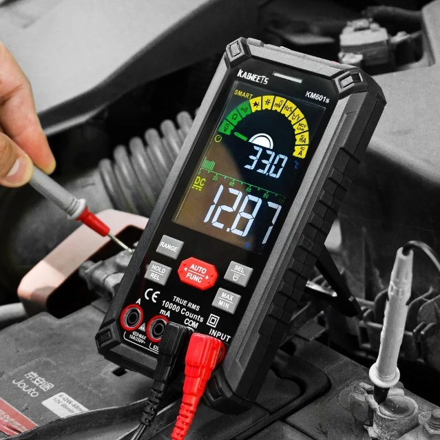
Step 2: Measure the source voltage
Place the red probe on the source positive terminal and the black probe on the source negative terminal. In a typical DC circuit, that usually means across the source terminals (e.g., Battery + to Battery -).
This reading shows the total voltage available from the source and gives you a baseline for the rest of the test.
Pro Insight: The Mechanics of Voltage Drop
A voltage drop test measures the difference in electrical potential between two points. Rather than memorizing “red to positive, black to negative,” focus on three ideas:
- Core Logic: It shows how much voltage is lost across the section between the two probes.
- Potential Direction: Current flows from higher potential to lower potential. When testing a section of a live circuit, the electrically upstream point is typically at a higher potential than the downstream point.
- What a Negative Reading Means: If the multimeter shows a negative reading, such as -0.5 V, it usually just means the probes are reversed and the red probe is on the lower-potential side. The reading is still accurate, the meter is not harmed, and the value itself is what matters.
Step 3: Measure the voltage at the load
Next, check how much voltage is actually reaching the component.
Depending on the type of circuit, that may mean measuring directly across the load while it is operating, or measuring the voltage available at the load terminals. This shows whether the component is receiving close to the voltage it should have during normal operation.
Step 4: Check the Power Side for Voltage Drop
Once you know the load is not getting enough voltage, check the supply path.
Place one probe on the Source (+) and the other probe on the Load Input (+). The meter will show exactly how much voltage is being "lost" in the wires and switches before it hits the load.
If the reading is higher than it should be, excessive resistance is present somewhere on the power side. That may point to a loose connection, corrosion, a damaged wire, a failing switch, a poor fuse connection or an undersized conductor.
Step 5: Check the Return Side for Voltage Drop
After checking the supply path, test the return path in the same way.
Place one probe on the Load Output (-) and the other probe on the Source (-) or Chassis Ground. If the reading is too high, the problem is on the ground or return side.
This step is critical because many voltage drop problems are caused by poor grounds or weak return connections, not by the supply side itself.
Step 6: Narrow the Fault to a Smaller Section
If you find excessive drop across a large section, do not stop there. Move the probes closer together and test smaller parts of that section one by one.
This is often the fastest way to isolate the exact problem point. For example, if the power side shows too much drop, test across the fuse, then the switch, then the connector, then the wire segment. If the return side is the problem, move step by step along the ground path until the high-resistance point becomes obvious.
Step 7: Interpret the Reading
The goal is to identify which section of the circuit is dropping more voltage than it should. In a healthy circuit, only a small amount of voltage should be lost along the supply and return paths. If one section shows an unusually high reading, that is the section to inspect.
For a typical 12V DC automotive circuit, use these general rules of thumb:
- 0.1V - 0.2V: Excellent/Normal for most wires and connections.
- 0.3V: Acceptable for some switches or longer wire runs.
- 0.5V or more: Significant resistance. This usually indicates a fault that needs repair.
Summary
A voltage drop test is the most effective way to find "hidden" resistance that a simple continuity test (Ohm test) might miss. By checking the circuit under load, you can pinpoint the exact connector or wire causing the issue, saving time and avoiding unnecessary parts replacement.

Leave a comment
All comments are moderated before being published.
This site is protected by hCaptcha and the hCaptcha Privacy Policy and Terms of Service apply.