


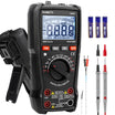

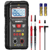
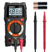
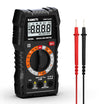

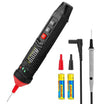


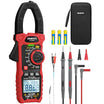
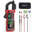
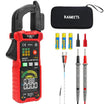




















A diode is designed to let current flow in one direction while blocking it in the other. This simple function makes it useful in rectifiers, power supplies, circuit protection, and many other electronic devices. But when a diode fails, it can cause problems that are not always easy to identify by looking at the component.
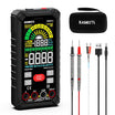
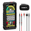
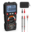
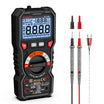
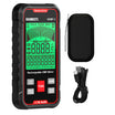
A multimeter provides a straightforward way to check whether a diode is working properly. Its diode test mode measures the voltage drop across the component in the forward direction and checks whether it blocks current in the reverse direction.
In this guide, you'll learn how to test a diode with a multimeter, interpret the readings, and identify common diode failures. We'll also cover what to do when you need to test a diode without removing it from a circuit board.
What You Need to Test a Diode
Before testing, gather the following:
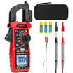
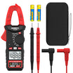
- A digital multimeter with a diode test function
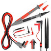
- A pair of multimeter test leads
- The diode you want to test
- A suitable tool for disconnecting one diode lead if necessary
Most digital multimeters include a dedicated diode test mode, usually marked with a diode symbol (→|). It may share a dial position with the continuity function.
Make sure your multimeter has this function before starting. Resistance mode can sometimes provide clues about a diode's condition, but diode mode gives a more useful reading because it measures the forward voltage drop directly.
Always disconnect power before testing a diode. If the diode is part of a circuit, unplug the equipment and discharge any capacitors according to the manufacturer's instructions. Never use resistance or diode test mode on an energized circuit.
How to Identify a Diode's Anode and Cathode
Before connecting the multimeter, you need to identify the diode's two terminals.
A standard diode has two terminals:
- Anode: The positive side of the diode.
- Cathode: The negative side of the diode.
On most conventional axial diodes, the cathode is marked with a stripe or band near one end of the component. The opposite end is the anode.
This marking is important because the diode only conducts normally when connected in the correct direction.
For other diode packages, such as surface-mount components, check the manufacturer's datasheet or component markings to identify the terminals. Don't assume that every diode uses the same physical orientation.
How to Check a Diode with a Digital Multimeter
The easiest way to check a diode is to use your multimeter's diode mode. You'll need to take two measurements: one in the forward direction and another in the reverse direction.
Step 1: Turn Off the Power
Disconnect the circuit or electronic device from its power source.
If you're testing a diode on a circuit board, make sure all stored electrical energy has been safely discharged. Capacitors can retain a charge even after the device has been unplugged.
For the most reliable result, disconnect at least one lead of the diode from the circuit. Other components connected in parallel can affect the measurement and make a good diode appear faulty.
Step 2: Set the Multimeter to Diode Mode
Turn the multimeter dial to the diode test setting.
Look for the diode symbol on the dial. On some models, this function shares a position with continuity mode, so you may need to press a function button to switch between them.
Insert the test leads into the correct terminals:
- Black lead: COM
- Red lead: VΩ or the terminal marked for voltage, resistance, and diode testing
The multimeter is now ready to measure the diode's forward voltage drop.
Step 3: Test the Diode in the Forward Direction
Place the red probe on the diode's anode and the black probe on its cathode.
In other words:
- Red probe → Anode
- Black probe → Cathode (the striped end on a typical axial diode)
Read the value displayed on the multimeter.
A functioning silicon diode will typically show a forward voltage drop of approximately 0.5–0.7 V. The exact reading depends on the diode type, the test current, and the temperature.
For example, a reading of 0.62 V generally indicates that a standard silicon diode is conducting in the forward direction.
This voltage drop is not the diode's supply voltage. It is the voltage measured across the diode while the multimeter applies a small test current.
Step 4: Test the Diode in the Reverse Direction
Now reverse the test leads:
- Red probe → Cathode
- Black probe → Anode
Check the display again.
A healthy diode should block current in this direction. Most digital multimeters will display OL (over limit or open circuit), indicating that the diode is not conducting under the meter's test conditions.
The exact display may vary by multimeter model, but the important point is that the reverse reading should indicate a blocked path rather than a normal forward voltage drop.
Step 5: Compare the Two Readings
A diode is generally considered functional when it conducts in the forward direction and blocks current in the reverse direction.
You should see two different results:
- Forward direction: A measurable voltage drop.
- Reverse direction: OL or another indication of an open circuit.
If both readings look the same, or neither reading matches the expected behavior, the diode may be damaged.
How to Read Diode Test Results
Understanding the readings is just as important as knowing how to connect the probes. Here are the most common results and what they mean.
| Multimeter Reading | What It Means |
|---|---|
| 0.5–0.7 V in forward direction, OL in reverse | Typical healthy silicon diode |
| 0.2–0.4 V in forward direction, OL in reverse | Common for a Schottky diode |
| OL in both directions | Possible open or damaged diode |
| Approximately 0 V in both directions | Possible shorted diode |
| Normal forward reading, but a measurable reverse reading | Possible leakage or a circuit-related reading; investigate further |
These ranges are general guidelines, not universal specifications. Always compare your readings with the diode's datasheet when available.
What Does a Good Diode Reading Look Like?
A standard silicon diode typically has a forward voltage drop between 0.5 V and 0.7 V.
Other diode types have different characteristics:
- Silicon diode: Usually 0.5–0.7 V.
- Schottky diode: Often 0.2–0.4 V.
- Germanium diode: Commonly around 0.2–0.3 V.
- LED: The forward voltage varies with color and semiconductor material. Many common LEDs measure approximately 1.5–3.3 V, although some types fall outside this range.
A higher or lower reading does not automatically mean the diode is faulty. Check the component specifications before deciding whether it has failed.
What Does OL Mean When Testing a Diode?
OL generally means that the multimeter detects an open circuit or that the measured value is beyond its display range.
When testing a diode, OL in the reverse direction is normally expected because the diode blocks current.
However, if the meter displays OL in both directions, the diode may have an internal open circuit. Repeat the test after checking the probe connections and, if necessary, isolating the diode from the circuit.
What Does 0.000 V Mean When Testing a Diode?
A reading close to 0 V in both directions can indicate a shorted diode.
A shorted diode allows current to pass in both directions instead of blocking reverse current.
Before replacing it, make sure the probes are making good contact and that other components in the circuit are not affecting the measurement.
How to Test a Diode Without Removing It from a Circuit
You can sometimes test a diode while it is still installed on a circuit board. However, the results are not always reliable.
Other components connected to the diode may create alternative current paths. These paths can change the readings and make a good diode appear shorted or leaky.
If you want to test a diode in place:
- Disconnect the equipment from its power source.
- Safely discharge any capacitors.
- Set the multimeter to diode mode.
- Place the probes across the diode in the forward direction.
- Record the reading.
- Reverse the probes and record the second reading.
- Compare both readings with the expected behavior.
If the results are inconsistent or unexpected, disconnect one lead of the diode and repeat the test.
This removes many of the parallel paths that can interfere with the measurement.
For troubleshooting work, testing a diode outside the circuit is generally the more dependable method.
Common Mistakes When Testing a Diode
Even with the correct multimeter setting, a few common mistakes can lead to misleading results.
Using Resistance Mode Instead of Diode Mode
Resistance mode measures resistance, while diode mode measures the forward voltage drop.
Some meters can provide useful information in resistance mode, but the results are less straightforward to interpret. Use the dedicated diode function whenever possible.
Reversing the Test Leads
If you connect the red probe to the cathode and the black probe to the anode, the meter should normally display OL.
This doesn't mean the diode is faulty. It simply means you're testing it in the reverse direction.
Always take measurements in both directions before drawing a conclusion.
Testing a Diode in an Energized Circuit
Diode mode is not designed for measuring components in a powered circuit.
An external voltage can interfere with the reading and may damage the multimeter or the equipment being tested.
Always disconnect power before performing the test.
Ignoring Other Components on the Circuit Board
A diode connected to resistors, capacitors, or other semiconductor components may produce readings that differ from its actual characteristics.
If the readings don't make sense, isolate one terminal and test again.
Frequently Asked Questions
Can You Test a Diode with a Multimeter Without Diode Mode?
Yes, but diode mode is the preferred method.
You can sometimes use resistance mode to check whether a diode conducts in one direction and blocks current in the other. However, the displayed resistance depends on the multimeter's test voltage and current, so it is not as easy to interpret as a forward voltage reading.
If your multimeter doesn't have a diode test function, consult its manual before attempting an alternative test.
Should a Diode Have Continuity in Both Directions?
No. A normal diode should conduct in the forward direction and block current in the reverse direction.
If your multimeter beeps in both directions during a continuity test, the diode may be shorted. However, continuity mode alone is not the most reliable way to evaluate a diode. Switch to diode mode and compare the two readings.
Can a Bad Diode Still Show a Normal Forward Voltage?
Yes. A diode can show a normal forward voltage drop but still have excessive reverse leakage or fail under higher voltage or current conditions.
A basic multimeter test checks the diode under a limited set of conditions. It cannot fully evaluate its performance under the operating conditions of the actual circuit.
For more demanding applications, additional testing equipment may be necessary.
How Do You Test an LED with a Multimeter?
You can test many LEDs using diode mode.
Place the red probe on the anode and the black probe on the cathode. A functioning LED may show a forward voltage reading and glow faintly, depending on the multimeter's test current and the LED type.
Reverse the probes, and the meter should normally display OL.
Some LEDs require a higher forward voltage than a basic multimeter can provide. If the display shows OL in both directions, check the LED specifications before assuming it is defective.
Can You Test a Zener Diode with a Multimeter?
Yes, but a standard diode test only checks its forward behavior.
A Zener diode behaves like a regular diode in the forward direction. Its defining characteristic is that it allows current to flow in the reverse direction once the reverse voltage reaches its specified Zener breakdown voltage.
A typical multimeter cannot generate the reverse voltage needed to test that breakdown characteristic. You'll need an appropriate power supply and a current-limiting resistor to test the Zener voltage safely.
Final Thoughts
Testing a diode with a multimeter comes down to checking how it behaves in two directions. A healthy diode should show a forward voltage drop and block current when the probes are reversed.
Remember to use diode mode, disconnect power before testing, and isolate one diode lead when other circuit components may affect the readings.
With these basic checks, you can identify many common diode failures without replacing components unnecessarily. A digital multimeter with a reliable diode test function makes this process much easier for everyday electronics troubleshooting.


Leave a comment
All comments are moderated before being published.
This site is protected by hCaptcha and the hCaptcha Privacy Policy and Terms of Service apply.